Privacy statement: Your privacy is very important to Us. Our company promises not to disclose your personal information to any external company with out your explicit permission.
Model No: NSO4GU3AB
Transportasi: Ocean,Air,Express,Land
Jenis pembayaran: L/C,T/T,D/A
Inkoterm: FOB,EXW,CIF
4GB 1600MHz 240-pin DDR3 UDIMM
Sejarah Revisi
|
Revision No. |
History |
Draft Date |
Remark |
|
1.0 |
Initial Release |
Apr. 2022 |
|
![]()
Tabel Informasi Pemesanan
|
Model |
Density |
Speed |
Organization |
Component Composition |
|
NS04GU3AB |
4GB |
1600MHz |
512Mx64bit |
DDR3 256Mx8 *16 |
Keterangan
Hengstar Unbuffered DDR3 SDRAM DIMMS (Tingkat Data Ganda DRAM DRAM DUAL MODUS DUAL IN-LINE) adalah modul memori operasi berkecepatan tinggi yang rendah yang menggunakan perangkat SDRAM DDR3. NS04GU3AB adalah 512m x 64-bit peringkat 4GB DDR3-1600 CL11 1.5V SDRAM Produk DIMM Unbuffered, berdasarkan komponen FBGA enam belas 256m x 8-bit. SPD diprogram ke Jedec Standard Latency DDR3-1600 waktu 11-11-11 pada 1.5V. Setiap DIMM 240-pin menggunakan jari kontak emas. SDRAM Unbuffered DIMM dimaksudkan untuk digunakan sebagai memori utama ketika diinstal dalam sistem seperti PC dan workstation.
Fitur
Pasokan kekuatan: VDD = 1.5V (1.425V hingga 1.575V)
VDDQ = 1.5V (1.425V hingga 1.575V)
800MHz FCK untuk 1600MB/dtk/pin
8 bank internal independen
Latensi CAS yang dapat diprogram: 11, 10, 9, 8, 7, 6
Latensi aditif yang dapat diprogram: 0, cl - 2, atau cl - 1 jam
8-bit pre-fetch
Burst Length: 8 (Interleave Tanpa Batas, Sequential Dengan Alamat Awal "000" saja), 4 dengan TCCD = 4 yang tidak memungkinkan Baca atau Tulis dengan mulus [baik dengan cepat menggunakan A12 atau MRS]
Bi-directional diferensial data strobe
Calibration brasi internal (self); Kalibrasi mandiri internal melalui zq pin (RZQ: 240 ohm ± 1%)
Ten Die Pengakhiran Menggunakan Pin ODT
Periode refresh rata -rata 7.8us pada lebih rendah dari tCase 85 ° C, 3,9us pada 85 ° C <tCase <95 ° C
Synchronous Reset
Kekuatan drive output data yang dapat disesuaikan
Topologi FLY-BY
PCB: Tinggi 1.18 ”(30mm)
Bohs yang sesuai dan bebas halogen
Parameter waktu utama
|
MT/s |
tRCD(ns) |
tRP(ns) |
tRC(ns) |
CL-tRCD-tRP |
|
DDR3-1600 |
13.125 |
13.125 |
48.125 |
2011/11/11 |
Tabel alamat
|
Configuration |
Refresh count |
Row address |
Device bank address |
Device configuration |
Column Address |
Module rank address |
|
4GB |
8K |
32K A[14:0] |
8 BA[2:0] |
2Gb (256 Meg x 8) |
1K A[9:0] |
2 S#[1:0] |
Deskripsi pin
|
Symbol |
Type |
Description |
|
Ax |
Input |
Address inputs: Provide the row address for ACTIVE commands, and the column |
|
BAx |
Input |
Bank address inputs: Define the device bank to which an ACTIVE, READ, WRITE, or |
|
CKx, |
Input |
Clock: Differential clock inputs. All control, command, and address input signals are |
|
CKEx |
Input |
Clock enable: Enables (registered HIGH) and disables (registered LOW) internal circuitry |
|
DMx |
Input |
Data mask (x8 devices only): DM is an input mask signal for write data. Input data is |
|
ODTx |
Input |
On-die termination: Enables (registered HIGH) and disables (registered LOW) |
|
Par_In |
Input |
Parity input: Parity bit for Ax, RAS#, CAS#, and WE#. |
|
RAS#, |
Input |
Command inputs: RAS#, CAS#, and WE# (along with S#) define the command being |
|
RESET# |
Input |
Reset: RESET# is an active LOW asychronous input that is connected to each DRAM and |
|
Sx# |
Input |
Chip select: Enables (registered LOW) and disables (registered HIGH) the command |
|
SAx |
Input |
Serial address inputs: Used to configure the temperature sensor/SPD EEPROM address |
|
SCL |
Input |
Serial |
|
CBx |
I/O |
Check bits: Used for system error detection and correction. |
|
DQx |
I/O |
Data input/output: Bidirectional data bus. |
|
DQSx, |
I/O |
Data strobe: Differential data strobes. Output with read data; edge-aligned with read data; |
|
SDA |
I/O |
Serial |
|
TDQSx, |
Output |
Redundant data strobe (x8 devices only): TDQS is enabled/disabled via the LOAD |
|
Err_Out# |
Output (open |
Parity error output: Parity error found on the command and address bus. |
|
EVENT# |
Output (open |
Temperature event: The EVENT# pin is asserted by the temperature sensor when critical |
|
VDD |
Supply |
Power supply: 1.35V (1.283–1.45V) backward-compatible to 1.5V (1.425–1.575V). The |
|
VDDSPD |
Supply |
Temperature sensor/SPD EEPROM power supply: 3.0–3.6V. |
|
VREFCA |
Supply |
Reference voltage: Control, command, and address VDD/2. |
|
VREFDQ |
Supply |
Reference voltage: DQ, DM VDD/2. |
|
VSS |
Supply |
Ground. |
|
VTT |
Supply |
Termination voltage: Used for control, command, and address VDD/2. |
|
NC |
– |
No connect: These pins are not connected on the module. |
|
NF |
– |
No function: These pins are connected within the module, but provide no functionality. |
Catatan : Tabel deskripsi pin di bawah ini adalah daftar komprehensif dari semua pin yang mungkin untuk semua modul DDR3. Semua pin terdaftar Mei tidak didukung pada modul ini. Lihat penugasan PIN untuk informasi khusus untuk modul ini.
Diagram blok fungsional
Modul 4GB, 512MX64 (2rank X8)


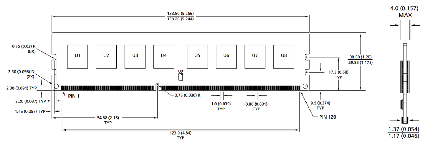
Dimensi modul
Tampak depan

Tampak depan

Catatan:
1. Semua dimensi dalam milimeter (inci); Max/Min atau tipikal (Typ) di mana dicatat.
2.Toleransi pada semua dimensi ± 0,15mm kecuali ditentukan lain.
3. Diagram dimensi hanya untuk referensi.
Kategori Produk : Aksesori Modul Cerdas Industri


Privacy statement: Your privacy is very important to Us. Our company promises not to disclose your personal information to any external company with out your explicit permission.

Fill in more information so that we can get in touch with you faster
Privacy statement: Your privacy is very important to Us. Our company promises not to disclose your personal information to any external company with out your explicit permission.